Data Rate Status

The Data Rate Status icon displays the the Pattern Generator status having to do with the clocking of data bits, and allows the user to select the clock rate and source for various parts of the Pattern Generator.
All clocking inside the Pattern Generator is synchronous to one data rate. This overall data clocking rate can be set by either the internal clock or the external clock. If more than one clock source is selected, the user must make sure that these clocks are all synchronous. It is possible to add stress, for example, to the internal clock that comes out the front panel OUTPUT clock and then to feed this stressed clock back into the ExtB input for use in clocking out pattern bits.
There are four sub-areas of the Pattern Generator that require a clock source to be selected. This includes the clocking source for Channel 0, Channel 1, the front panel OUTPUT clock, and the clocking used for the Calibration input.
There are three possible sources of clocking. They are not completely independent. A user can select between the (Internal Clock or ExtA clock) and the ExtB clock. That is, if Internal Clock is selected as any clock source, then ExtA cannot be chosen. Similarly, if ExtA is chosen as any clock source, then Internal Clock cannot be chosen. ExtB clock source can be chosen at any time.
For this reason, for example, the Internal Clock can be directed to the front panel OUTPUT connectors and then fed back into the ExtB clock input to be used to clock Channel 0 and/or Channel 1. We could not loopback the clock to the ExtA input, because the Internal Clock was already being used.
In addition to choosing the input source for the four clocks, users can also select a divide-ratio for the front panel OUTPUT clock and the Calibration input clocking. Divide ratio values are based on the data rate. A Div2 OUTPUT clock for a 10 Gbps signal will oscillate at 5 GHz. A Div16 setting on the Calibration clock divider on a 10 Gbps signal will mean the bits presented to the Calibration input will be sampled at 625 MHz, creating a 625 Mbps measurement stream.
|
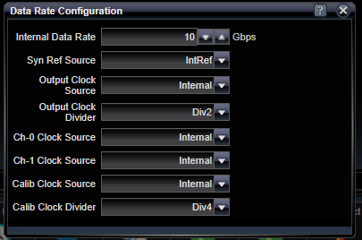
Internal Data Rate |
|
|
Gbps |
Data rate of the internal synthesizer measured in Gbps. |
|
Syn Ref Source |
|
|
IntRef / ExtRef |
Selection of internal or external 100 Mhz reference for the internal synthesizer. External reference is supplied on the rear of the unit. The internal reference is also available on the rear of the unit and can be used by another Pattern Generator if synchronization is required. |
|
Output Clock Source |
|
|
Internal / ExtA / ExtB |
Selection of the clock source for the front panel OUTPUT Clock+ and Clock- signals (see limitation on Internal/ExtA described above). |
|
Output Clock Divider |
|
|
Div2 / Div4 / Div8 / Div16 |
Divide ratio for clocking signals coming out the front panel OUTPUT clock. Ratio is with respect to the Data Rate of the Pattern Generator. |
|
Ch-0 Clock Source |
|
|
Internal / Ext A / Ext B |
Selection of the clock source for Channel 0 data bits (see limitation on Internal/ExtA described above). |
|
Ch-1 Clock Source |
|
|
Internal / Ext A / Ext B |
Selection of the clock source for Channel 1 data bits (see limitation on Internal/ExtA described above). |
|
Calib Clock Source |
|
|
Internal / Ext A / Ext B |
Selection of the clock source for the bit sampling clock used on the Calibration input (see limitation on Internal/ExtA described above). |
|
Calib Clock Divider |
|
|
Div2 / Div4 / Div8 / Div16 |
Divide ratio for Calibration input clocking rate. Ratio is with respect to the Data Rate of the Pattern Generator. Users should select this divide ratio to assure that the clocking rate on the Calibration input remains below 2.5 Gbps. A Div2 setting implies that the Calibration input is sampling every second bit in the stream. The speed limitation would imply that that Div2 setting could be used for system Data Rate application up to 5 Gbps. For 28 Gbps applications, a Div16 setting must be used and the Calibration bit error rate tester would sample every 16th data bit at an overall rate of 1.75 Gbps. PRBS patterns work well when divided by factors of two; however, user-defined patterns that are divided by a factor of two must be carefully interpreted. For example, a 101010 pattern divided by a factor of two would yield either 111111 or 000000, depending on initial conditions. |
See Also