Understanding the Bit Error Location Analyzer
The Bit Error Location Analyzer measures two differential input signals that can be independent, or combined. Combined analysis can either simply add the two channel's error statistics together, or the two channels can be considered as a bit-interleaved PRBS channel where synchronization depends on the bit-interleave of the two channels being recognized as a PRBS pattern. This mode is more sophisticated because the analyzer also performs bit-shifting operations between the two channels in order to locate the proper bit-phase in addition to bit-interleave for synchronization with a PRBS pattern.
In order to perform measurements, the analyzer is provided an external clock that may be full-rate or half-rate. By performing a clock reset operation, the device scans the incoming clock signal and locates an appropriate threshold level for detecting the clock. Once a clock is detected, the measured value is displayed. With an incoming clock, each data channel can then be Autoset to determine an appropriate sample point for interpreting the bits of the incoming signals. The sample point is comprised of a voltage threshold, like the clock, and a time offset relative to the clock. These values are automatically set when you perform the Autoset function.
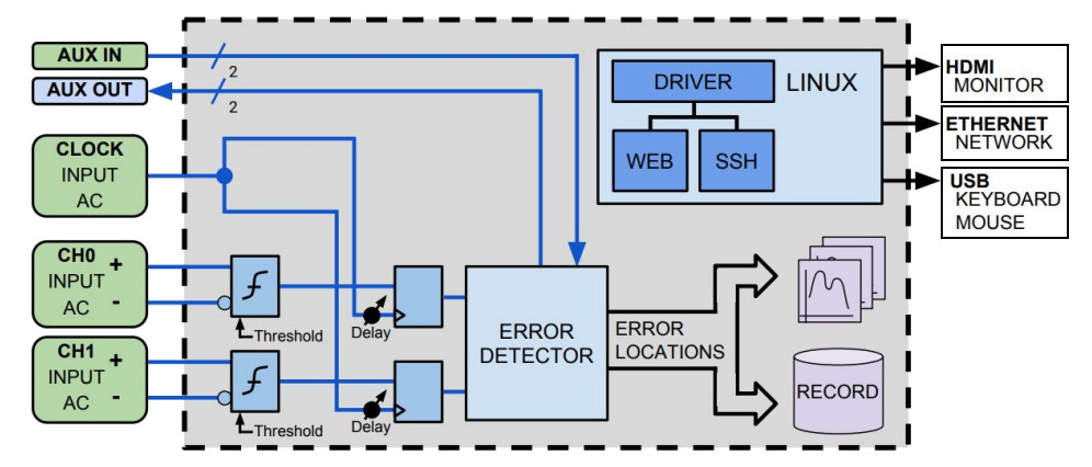
BIT ERROR LOCATION ANALYZER BLOCK DIAGRAM
What's Inside
Inside the Bit Error Location Analyzer there is high-bandwidth sampling mechanisms for both channels and considerable logic for recognizing and synchronizing with incoming patterns. Patterns may be synthesized in real-time - such as PRBS patterns, all one's, or all zeros, or they may be stored in 128-bit word memory. Upon synchronization with the incoming data pattern, error detection is performed by comparing the received bit stream with a recreated bit stream based on pattern synchronization. In addition to simple error testing and error counting, the Bit Error Location Analyzer hardware can also create a stream of error locations for further analysis. A number of Error Location applications are provided to study error syndromes that can be detected based on error locations. For example, Burst length histogram, Error-free length histogram, Errors modulo a fixed number or Errors modulo a trigger input signal. These features provide excellent diagnostics to understand the errors in a channel.
Memory patterns have two synchronization modes. In the basic mode, the user pre-fills the memory with the pattern to be recognized. Then, when synchronization is requested, the device will cycle-through all bit-phases of the memory contents to determine if synchronization can be achieved with the incoming bit stream at any of the bit phases. In the second mode, the user is not required to pre-fill the memory, but must provide a number of words upon which the pattern is expected to repeat. Then, when synchronization is requested, that many words is grabbed from the incoming bit stream and a second and third copy of that many words is compared with the first grab. If no mismatches occur between the two subsequent comparisons with the original grab, then synchronization is declared. This second method is much faster than the first, and is very often all that is required for excellent memory-based pattern BER testing.
All of this is controlled via a Linux computer that provides for TCP/IP socket automation and web-browser based user interface control.