Calibration Input - Deferred Eye
When a Deferred Eye sampler is chosen, the specific means to control the horizontal sampling time and the vertical sampling threshold needs to be defined. Selections on this tab allow for these settings.
In general, horizontal control is accomplished by changing the Ch0-to-Ch1 timing relationship (assuming the clock and data test signals are derived from the Ch0 and Ch1 Pattern Generator lanes). This can be done by adding delay to one lane and/or subtracting delay from the other lane. Using both delays allows more range in the sampling time value. In some applications, only the clock or only the data can be shifted in time and so you can only use one delay channel.
Vertical control is done by adding DC voltage offset to the data waveform. This can be done only when the input data is DC coupled to the actual customer sampling device. In some special cases, it may be possible to rework a test board to allow a DC signal to sum into the test signal at the input of the customer flip-flop. For this reason, we have provided for operating based on DATA from one Pattern Generator channel but using the DC offset from the other Pattern Generator channel. This is a challenging application, so contact us for help in the case of sampling deferred eyes in AC-coupled applications.
|
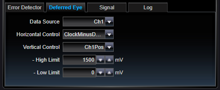
Data Source |
|
|
Ch0 / Ch1 |
Select either Ch0 or Ch1. This the the Pattern Generator channel that will be used to create data for the Deferred Eye. |
|
Vertical Control |
|
|
Ch0Pos / Ch0Neg / Ch1Pos / Ch1Neg |
This is the Pattern Generator leg (one of four possible) whose DC offset will be used to create the vertical threshold control. It is typically the case that this will be the same leg where the data is coming from, but it is not specifically required. Choosing a different leg can give a separate control which may be able to be reworked into a test circuit for sampling deferred eyes. |
|
Horizontal Control |
|
|
ClockDelay / NegDataDelay / ClockMinusDataDelay |
Horizontal control provides the time axis for sampling. Deferred eyes sample at different times by delaying the test signal, the clock signal, or both. The three choices here are ClockDelay, NegDataDelay and ClockMinusDataDelay. Each of these move the sampling time for the Deferred eye. Which to choose depends on your application. If one Pattern Generator channel is used for clock and the other channel is used for Data, then the ClockMinusDataDelay setting will allow for the larges variable delay timebase range. |
See Also