Calibration Input Status
The Calibration Input Status icon displays the current Configuration status, and allows the user to set up parameters having to do with the Calibration Input. Specifically, it allows a user to define the Sampler type (point of the logical decision) and then to further define settings needed for the Error Detector, Deferred Eye operation, and the Calibration input signal conditions.
|
|
Calibration Input Disabled |
|
|
Calibration Input Enabled |

The Calibration Input is an AC or DC coupled, single-ended input that can be used to measure bit error rate, draw BER bathtubs, and draw eye diagrams. This is helpful for self-calibration of the Pattern Generator's outputs after going through customer circuits or cables.
The Calibration input sampling clock has a maximum rate of 2.5 GHz, but the analog bandwidth extends much higher, meaning that it can measure sub-sampled bit error and eye diagramming data for applications at the full speed of the Pattern Generator. It does this by looking at every Nth bit (for bit error rate measurements) or triggering at a slow sub-rate (for eye diagrams). This is much like the behavior of an oscilloscope that can draw an eye diagram when triggered at the bit-rate or at sub-octaves of this rate. There are limitations from this constraint, but this generally provides excellent feedback for self-calibration.
The Calibration input consists of a high-performance SiGe flip-flop with variable logic threshold, variable AC/DC termination, and variable delay. Each of these settings are described below.
Furthermore, for the highly specialized application where a customer's flip-flop sampling circuit can have its logic threshold shifted by shifting the voltage offset of the applied data, and whose sample timing can be controlled by the clock-to-data timing relationship as it leaves our Pattern Generator, a "DeferredEye" sampler can be configured to allow making bit error rate, bathtub curves, and eye diagrams at the customer's sampling point (rather than at the sampling point inside our Calibration Input). In this application, we defer our internal bit decision to the customer's bit decision and perform our analysis using his pre-decided data.
In order to support measurements and auto-align functions, the anticipated sub-rate ratio of the eye bit periods being sampled needs to be specified. This is typically defined when the Calibration clocking divide ratio is selected, but this is not necessary. Customers' signals with other divide ratios can be supported.
A typical application for the Calibration Input is when studying a quarter-rate loopback signal coming from a transceiver. The Transceiver (and our Pattern Generator) may operate at 8.4 Gbps, but the transceiver may support at 1/4 rate loopback of every fourth bit. This loopback stream would be running at 2.1 Gbps. The Pattern Generator's Calibration clock input divider would be set to Div4 and BER, Bathtub, and Eye Diagramming of the Calibration input would be supported. The eye diagrams and bathtub analysis would operate based on the decisions made at the full 8.4 Gbps input of the transceiver — not the sub-rate of the Pattern Generator's calibration input.
If this Transceiver was DC-coupled, the logic threshold within the eye diagram could be virtually moved by moving the output DC offset such that the test pattern would move up and down against the Transceiver's fixed voltage threshold. This would provide a voltage-axis control to the threshold. Similarly, if the Transceiver supported a forwarded clock along with the test data stream (as in DDR memory), then shifting the phase relationship at the Pattern Generator's output would provide a time-axis control to the sampling point. These two controls are all that are needed to draw two-dimensional analysis such as differed eye diagrams.
This is a unique way to study the eye diagram at a point in electrical processing that may not be available to probe.
It is important to note that this deferred sampler concept will not work in many application such as those that recover clocking information from the data itself. It is highly specialized and works well in stand-alone or embedded flip-flops. In these cases, the normal Calibration Input sampler must be used.
|
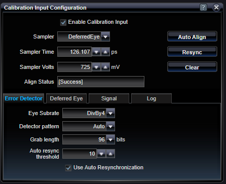
Enable Calibration Input |
|
|
On / Off |
Enable or Disable the use of the Calibration Input |
|
Sampler |
|
|
CalInput / DeferredEye |
Set which sampler type will be used. CalInput is the normal type of error detector input typically thought of for bit error rate testers. DeferredEye sampler is highly specialized and allows performing analysis at an up-stream decision point (see above). |
|
Sampler Time |
|
|
ps |
Time delay within the eye to make a sample decision. This refers to the time delay at the point of sample which may be at the internal sampler (CalInput) or the deferred sampler (DeferredEye). |
|
Sampler Volts |
|
|
mV |
Voltage threshold within the eye to make a sample decision. This refers to the threshold at the point of sample which may be at the internal sampler (CalInput) or the deferred sampler (DeferredEye). |
See Also
See Also