Trigger Output Status

The Trigger Status icon displays the current Trigger status, and allows the user to define the operation of the two front panel Trig-0 and Trig-1 signals.
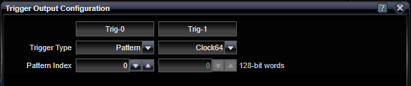
This menu allows independent setting of either a pattern trigger or a clock trigger for both the Trig-0 (for Channel 0) or the Trig-1 (for Channel 1) output. When pattern triggers are selected, a pattern index can be set to offset the trigger within the pattern. The resolution of pattern index values is 128 bits.
When used to trigger an oscilloscope, pattern triggers allow for viewing single-valued waveforms that show the output at a particular spot within the pattern. By changing the pattern index, one can step through the data pattern. Clock patterns used for triggers will allow oscilloscopes to draw eye diagrams.
It is important to note that the clock trigger is not at the bit rate of the Pattern Generator. Instead, it outputs a divided-down clock (clock divide ratio is 1:64). This means that there are potentially 64 unique eyes present in an eye diagram triggered by this signal. When looking at PRBS data, all eyes would see all data transitions; however, User patterns could be constructed that would not yield a complete eye diagram on such a clock pattern used as a trigger.
|
Trigger Type |
|
|
Pattern / Clock64 |
Selection for Pattern or Clock64 Trigger type (see above) |
|
Pattern Index |
|
|
128-bit words |
If Trigger Type is set for "Pattern", users can supply a pattern index value to shift the phase of the output Trigger. |
See Also