Pattern Generator Application
![]()
The Pattern Generator application gives easy access to a number of the controls that define the output data on each channel. This is grouped into sections for setting the Clocking, Pattern, Signal Levels and Pre-emphasis. In addition, the outputs for both channels can be turned "ON" or "OFF" using the two buttons on the bottom.
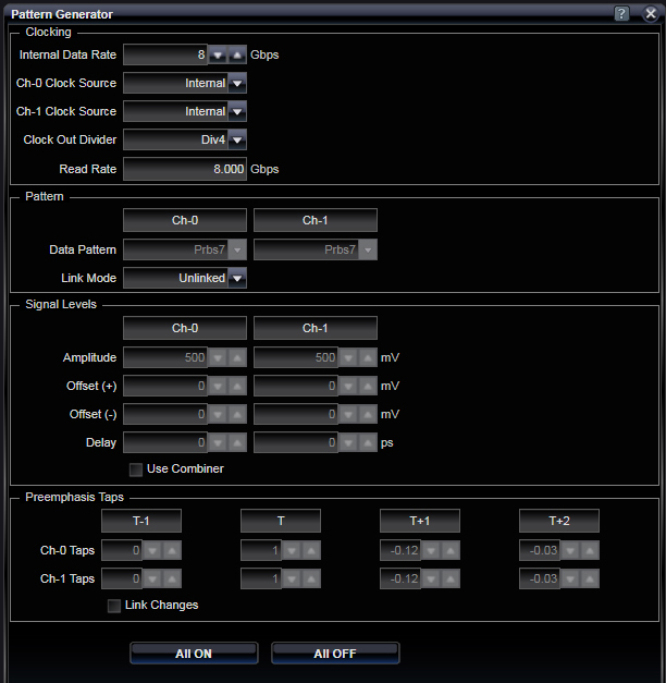
All of these controls (and more) are also available in the individual Ch-0 / Ch-1 Status items in the Status Bar.
Clocking
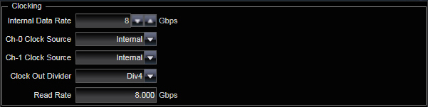
The Internal Data Rate entry sets the internal clocking rate of the Pattern Generator. It is shown in Gpbs (Gigabits per second).
Ch-0, Ch-1 Clock Source - You can choose for clocking to come from the internal synthesizer or either of the two Ext-A or Ext-B settings. Internal and ExtA are mutually exclusive throughout the Pattern Generator, so you can either use Internal or use Ext-A, but you cannot use both at the same time. Clock sources can be chosen for output channels (Ch-0, Ch-1) as well as for the Output clock and the internal Calibration channel sampler.
Clock Out Divider - The double-data rate front panel Output clock can be set to output a sub-octave of the data rate. Settings of DIV2, DIV4, DIV8 and DIV16 are supported. This is a divide ratio based on the data rate setting.
Read Rate - This is a read-only field that shows the measured data rate of the Pattern Generator.
|
Internal Data Rate |
|
|
0 - 28 GBps |
Internal clocking rate of the Pattern Generator |
|
Channel Clock Source |
|
|
Internal / ExtA / ExtB |
Select internal synthesizer or either ExtA or ExtB. Internal and ExtA are mutually exclusive throughout the Pattern Generator, so you can either use Internal or use ExtA, but you cannot use both at the same time. |
|
Clock Out Divider |
|
|
Div2 / Div4 / Div8 / Div16 |
Divide ratio based on the data rate setting |
|
Read Rate |
|
|
Gbps |
Measured data rate (read-only) |
|
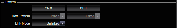
Pattern
Pattern - The two channels support different data patterns. It is not required to have the same data pattern on both channels (unless "linked" operation is selected). Patterns include popular pseudo-random bit sequences that repeat at various 2^N-1 bits in length (e.g., PRBS7 repeats every 127 bits). User RAM patterns are also supported and must be loaded into RAM before they are selected for transmission (see User Pattern control in bottom Status Bar). Link Mode - Link Mode allows you to operate in single-channel mode, to operate with both channels independent (unlinked), or to carefully output synchronized data between the channels. Synchronization can either allow both channels to transmit in parallel (linked: both patterns start and end at the same time) or interleaved. Interleaved streams intend for bits from the two channels to be bit-interleaved downstream to form a serial stream (e.g., a 2:1 multiplexer). Data Pattern |
|
|
PRBS7 / PRBS11 / PRBS13 / PRBS15 / PRBS20 / PRBS23 / PRBS31 / User / Ones / InvPrbs7 / InvPrbs11 / InvPrbs13 / InvPrbs15 / InvPrbs20 / InvPrbs23 / InvPrbs31 / InvUser |
Select pattern to be generated. Channels can support different data patterns unless "linked" operation is selected. Patterns include popular pseudo-random bit sequences that repeat at various 2^N-1 bits in length (e.g., PRBS7 repeats every 127 bits). User RAM patterns are also supported and must be loaded into RAM before they are selected for transmission (see User Pattern control in the Status Bar). |
|
Link Mode |
|
|
Ch0 / Ch1 / Unlinked / Linked / Interleaved |
Link Mode allows you to operate in single-channel mode, to operate with both channels independent (unlinked), or to carefully output synchronized data between the channels. Synchronization can either allow both channels to transmit in parallel (linked: both patterns start and end at the same time) or interleaved. Interleaved streams intend for bits from the two channels to be bit-interleaved downstream to form a serial stream (e.g., a 2:1 multiplexer). |
|
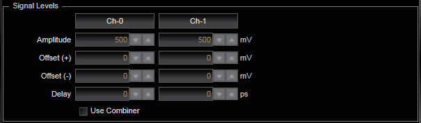
Signal Levels
Independent control of Amplitude, Offset+/- and Delay can be adjusted for each channel. Amplitudes and Offsets are specified in millivolts while delay is specified in picoseconds. For applications that use the passive PAM4 combiner, users may select the "Use Combiner" checkbox. In this case, the two independent controls are replaced with a single amplitude/offset/delay control as the instrument automatically distributes and times signals to both legs of the external PAM4 combiner. Amplitude |
|
|
mV |
Can be adjusted for each channel. |
|
Offset (+) / (-) |
|
|
mV |
Can be adjusted for each channel. |
|
Delay |
|
|
ps |
Can be adjusted for each channel. |
|
Use Combiner |
|
|
On / Off |
When the PAM4 Combiner is selected, the separate controls are replaced with a single amplitude/offset/delay control as the instrument automatically distributes and times signals to both legs of the external combiner. |
|
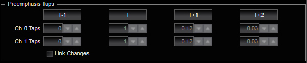
Preemphasis Taps Both output channels support four taps of programmable pre-emphasis and you can set the gain coefficients for each tap on each channel. Tap 1 is always 1.0 (the user's amplitude setting will set the overall signal amplitude). Other taps can be either positive or negative. By selecting the "Link Changes" check-box, both channels will use the same pre-emphasis settings.
T1 / T / T+1 / T+2 |
|
|
Ch0 / Ch1 |
Each output channel support four taps of programmable pre-emphasis. Set the gain coefficients for each tap on each channel. Tap 1 is always 1.0 (the user's amplitude setting will set the overall signal amplitude). Other taps can be either positive or negative. High-pass filters (typical of pre-emphasis) typically have the T-1, T+1 and T+2 values negative. Low-pass filters (which would cause more ISI) typically have T-1, T+1 and T+2 positive. |
|
Link Changes |
|
|
On / Off |
Link tap changes to both channels. |
|
Output Enable
All ON |
|
|
|
Turns on output from both channels. |
|
All OFF |
|
|
|
Turns off output from both channels. |

See Also
Pattern Generator Applications