Pattern Generator Quick Start
This Quick Start guide will help you set up your BitWise Pattern Generator quickly so you can begin making measurements.
To view a video introduction to the Pattern Generator, click here.
Required Equipment
- In the box
- BitWise Device
- Power Adapter and Cord
- Also required
- LAN
- LAN-connected computer running web browser
- Ethernet Cable
- Single-ended SMA to SMA Cable
- 50-Ohm SMA Terminator (optional)
Setting Up the Pattern Generator
- Make sure the power switch on the rear of the Pattern Generator is in the OFF position.
- You may use the banana jack on the rear panel to ground the device chassis.
- Plug your BitWise device into the network using the Ethernet cable.
- Use the provided power adapter and cord to plug your BitWise device into a power outlet.
- Use the power switch on the rear of the unit to turn the device ON. Wait for the device to initialize.
Wait for the Pattern Generator to Initialize
BitWise devices have an LED on the front panel called "READY". This LED provides status of the device's progress through the initialization process:
Power on: Green solid
Operating system initialized: Off
Device server initialized: Green single-blink
Web server initialized: Green double-blink
User interface website available: Green triple-blink
Initialization complete: Green solid
Access the User Interface Website
Use a computer connected to the same local area network as the device, access the user interface website by entering your device's IP address as the URL in your browser. For help finding your device's IP address, read the guide here.
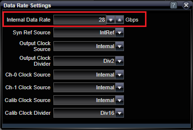
Set Data Rate
Use the internal synthesizer to create a clock that will be used to create the bits to be transmitted on Ch0 and Ch1 output connectors. Click on the Data Rate status panel to view the Data Rate Settings dialog and select the data rate you want. Notice a divided-down version of this clock also is transmitted on the Clock output connector.

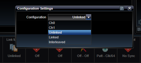
Set Channel Link Mode
Indicate that Ch0 and Ch1 should be considered independent by clicking on the Link Mode status panel to view the Configuration Settings dialog and select the configuration to be Unlinked.

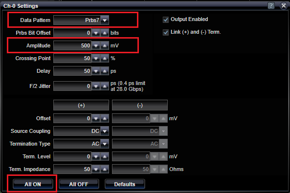
Set Data Pattern and Signal Amplitude and Turn-on Outputs
Configure the Ch0 output type by clicking on the Ch-0 status panel to view the Ch-0 Settings dialog. Select the desired data pattern and signal amplitude. Do the same for the Ch-1 status panel. Finally, turn on the channel outputs by pressing the All On button.

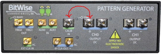
Loop Ch0 into Calibration Input
Find a short SMA-to-SMA cable and connect Ch-0 (+) output connector to the Calib input connector. Use this "loopback" wiring configuration to run a simple BER test.
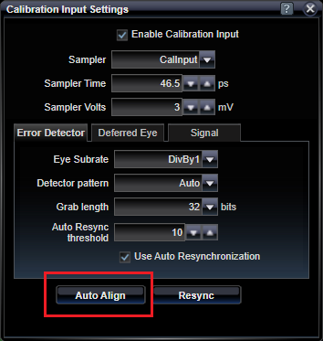
Auto-align Calibration Input Sampler
Before running a BER test, the Calibration input sampler must align itself with the incoming waveform to establish a delay and voltage threshold sampling point for testing. Click on the Cal Input status panel and press the Auto Align button and wait until the operation is completed.

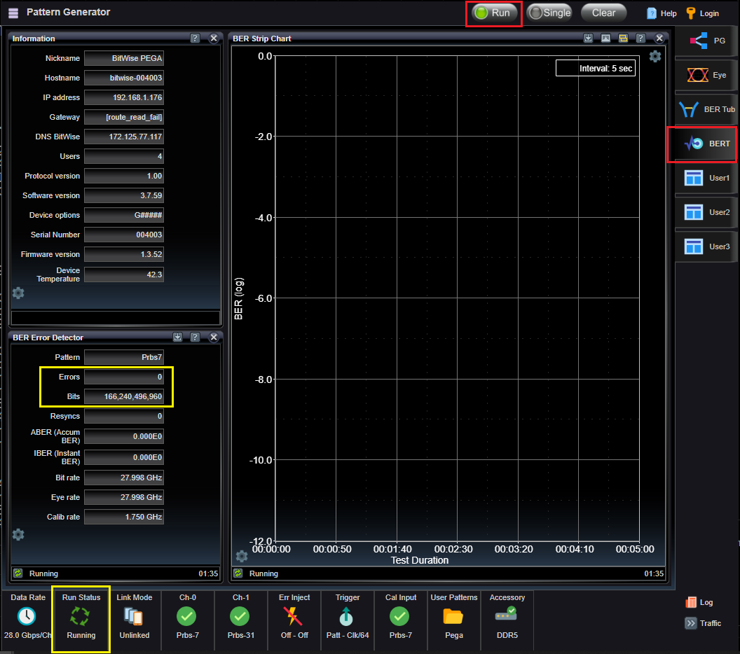
Run BERT Application
To run a BER test using the sub-rate calibration input, click on the right-hand BERT Tab to view the application space consisting of the Information, BER Strip Chart, and BER Error Detector applications. Then press the Run button on the top of the user interface to begin BER testing. You will notice the number of Bits climbing, and presumably no Errors. You will also notice an animation on the Run Status status panel indicating the Running state, on the bottom left. If you unscrew the connector a bit, maybe you can see some errors trickle in. The BER Strip Chart will show a chart of error rates at specified time intervals.
See Also