Auxiliary GPIO Status

The GPIO Status icon displays the current GPIO status, and allows the user to select what general purpose inputs and outputs may be used for. There are two auxiliary outputs that can be used to provide a variety of signals including the following:
|
Output Usage |
Description |
|
Ch0Pattern |
Pattern synchronization pulse occuring once per cycle for the repeating pattern detected on Ch-0. |
|
Ch1Pattern |
Pattern synchronization pulse occuring once per cycle for the repeating pattern detected on Ch-1. |
|
Ch0Error |
Stretched pulse occuring upon detection of an errored 128-bit word on Ch-0. |
|
Ch1Error |
Stretched pulse occuring upon detection of an errored 128-bit word on Ch-1. |
|
AnyError |
Stretched pulse occuring upon detection of an errored 128-bit word on either Ch-0 or Ch-1. |
|
WordClock |
128-bit word clock |
|
AuxLoopback |
The level provided as input to the corresponding GPIO input signal. Used for diagnostics purposes. |
|
Off |
Disabled. |
There are also two auxiliary inputs that are dedicated to specific purposes.
|
Input Usage |
Description |
|
Marker input, Dedicated to SMA1 |
Used with Error Location Analysis to provide an external trigger that can be associated with error locations. |
|
Blank input, Dedicated to SMA2 |
Used with Error Location Analysis and Error Location Analysis to mask error checking during specific blanked intervals sampled at 128-bit word boundaries. |
GPIO Status Icons
|
|
Local Source |
|
|
Remote Source |
|
|
External Source |


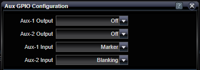
GPIO Configuration Settings
Configures two auxiliary outputs to provide a variety of types of signals, and two auxiliary inputs to be used for a variety of purposes.
|
Aux-1 Output |
|
|
CH0 Pattern, CH1Pattern, CH0Error, CH1Error, AnyError, WordClock, AuxLoopback, Off |
Select Aux-1 output purpose |
|
Aux-2 Output |
|
|
CH0 Pattern, CH1Pattern, CH0Error, CH1Error, AnyError, WordClock, AuxLoopback, Off |
Select Aux-2 output purpose |
|
Aux-1 Input |
|
|
Marker |
Indicates Aux-1 input is dedicated for use as Marker input. Used with Error Location Analysis to provide an external trigger that can be associated with error locations. Not used at this time. |
|
Aux-2 Input |
|
|
Blanking |
Indicates Aux-2 input is dedicated for use as Blanking input. Used with Error Location Analysis and Error Location Analysis to mask error checking during specific blanked intervals sampled at 128-bit word boundaries. |
See Also