Combined Channel Status

The Combined Channel Status icons display the current combined channel status, and provides properties to control the inter-channel synchronization operation.
Combined Channel Status Icons
|
|
Unlinked |
|
|
Linked |
|
|
Both channels synchronized as interleaved pattern |
|
|
Both channels are not synchronized as interleaved pattern |


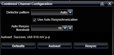
Combined Channel Configuration Settings
Use these setting to configure the combined channels' synchronization parameters and to automatically set both channels' sampling points.
|
Detector Pattern |
|
|
Auto, AllZeroes, Allones, Prbs7, Prbs11, Prbs13, Prbs15, Prbs20, Prbs 23, Prbs31, RamGrab, RamShift, InvPrbs7, InvPrbs11, InvPrbs13, InvPrbs15, InvPrbs20, InvPrbs23, InvPrbs31, InvRamGrab, InvRamShift |
Selects the pattern detection mode in use for the combined channel. This selection is only available if the Link Mode Status is selected to be Interleaved. Detection may be set to look for a specific pattern type, or it may be set to Auto, which searches through all the available pattern types to find one that synchronizes. There are two User Pattern memory Ram pattern modes. In Ram Grab mode, the system grabs the specified Ram Words number of 128-bit words from the associated input bit-stream and compares two subsequent grabs of the same number of words with the first. If all compare okay, then a successful synchronization is declared. In Ram Shift mode, you must previously load the detector User Pattern memory with contents by deploying a selected user pattern from the User Patterns Status configuration controls. Synchronization is achieved when the incoming bit stream compares precisely with the user pattern memory contents. This mode of synchronization can require a few seconds depending on the size of the user pattern. |
|
Auto Resync Threshold |
|||||
|
Decimal, 1 - 254 |
Selects the automatic resynchronization threshold level. This is the number of consecutive errored 128-bit words required to trigger a new automatic synchronization attempt. The lower the number, the more-sensitive the automatic resynchronization trigger becomes. |
||||
Resync Button |
|||||
|
Command Button |
Manually triggers an resynchronization attempt with the incoming data stream. If a specific data pattern is selected as the Detector Pattern, then only that type of pattern is searched for. If Auto pattern is selected, then all the available patterns are searched, starting with the one that was most-recently synchronized with. |
||||
See Also