STEPScope® Quick Start
This Quick Start guide will help you set up your BitWise STEPScope quickly so you can begin making measurements.
To view a video introduction to the STEPScope, click here.
Required Equipment
- In the box
- BitWise Device
- Power Adapter and Cord
- Also required
- LAN
- LAN-connected computer running web browser
- Ethernet Cable
- Calibration Terminations (see: Note)
- Appropriate Cables
Setting Up the STEPScope
- Make sure the power switch on the rear of the STEPScope is in the OFF position.
- You may use the banana jack on the rear panel to ground the device chassis.
- Plug your BitWise device into the network using the Ethernet cable.
- Use the provided power adapter and cord to plug your BitWise device into a power outlet.
- Use the power switch on the rear of the unit to turn the device ON. Wait for the device to initialize.
Wait for the STEPScope to Initialize
BitWise devices have an LED on the front panel called "READY". This LED provides status of the device's progress through the initialization process:
Power on: Green solid
Operating system initialized: Off
Device server initialized: Green single-blink
Web server initialized: Green double-blink
User interface website available: Green triple-blink
Initialization complete: Green solid
Access the User Interface Website
Use a computer connected to the same local area network as the device, access the user interface website by entering your device's IP address as the URL in your browser. For help finding your device's IP address, read the guide here.
Performing Calibrations
The STEPScope includes two kinds of carefully engineered self-calibration steps. The platform calibrations are used to assure the voltage and time accuracy of all measurements. The platform calibrations consist of noise calibration, a delay calibration and a flatness calibration. These are executed by pressing the “Calibrations” button on the lower status bar in the user interface. These calibrations take a couple minutes and should be performed once every few months or at the beginning of any critical measurements. The second kind of calibrations are the analysis-specific calibrations. These calibrations include cabling present in the measurement system so that the impact of the cables can be removed. These calibrations must be re-run every time the cabling changes or the temperature of the test system changes. These calibrations consist of attaching 50-ohm loads, SHORTs or THRUs to the cables and executing the calibration step. Each calibration takes less than a minute to perform.
Platform Calibrations
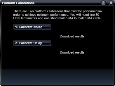
Platform Calibrations should be performed once the STEPScope is set up in your lab. To access the Platform Calibrations menu, click on the Calibration button in the Status Bar on the bottom of the UI.

Follow the instructions in the Platform Calibrations menu. You will need two 50-Ohm terminators and a short female SMA-SMA cable.
Once you've completed all three calibrations, click Save Calibrations.
Make Measurements
Step Response
After completing the Platform Calibrations, you can use the Step Response App. To learn more about how the STEPScope makes these measurements, read What's Inside.
TDR
Before making TDR measurements, you must perform the TDR calibrations. These calibrations must be performed any time the test cabling changes, or the test temperature changes.
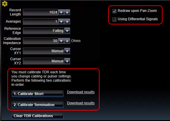
To perform TDR calibrations, click on the TDR Interface Tab. This will bring up the TDR App and the Information App. Click on the TDR Settings wheel ![]() below the TDR chart. This will open the TDR Settings.
below the TDR chart. This will open the TDR Settings.
Select the Differential Signals checkbox if you will be performing differential measurements. For single-ended measurements, leave this checkbox unchecked. Follow the instructions in the UI to complete the two calibration steps.
1. Calibrate Short
2. Calibrate Termination
After calibration, the TDR app can be used to measure impedance along an electrical path.
Example: If you wish to test the impedance along a single long cable, you will first do TDR calibrations for a single-ended measurement (terminating the unused TDR- leg with 50-Ohms).
Next, the test cable will be attached to the TDR+ port. If the cable is especially long, the pulser width setting must be changed so that steps sent down the cable do not interfere with each other. The end of the cable may be terminated with a short, open, or matched terminator. However, because a matched terminator will be indistinguishable from the cable, leaving the cable open will allow the user to see where the cable ends in the measurement.
Finally, the TDR app will display a chart of Ohms vs. Time. The time = 0 point corresponds to the calibration plane, which was set during the Short Calibration. If the end of the cable was left open, then that point will be characterized by a sharp upwards step in the chart.
If you wish to measure the impedance of a device away from the front panel of the STEPScope, then you can move the calibration plane to the end of your cable by performing TDR calibrations there. This is true for single-ended or differential measurements.
 TDT
TDT
Before making TDT measurements, you must perform the TDT calibrations. These calibrations must be performed any time the test cabling changes, or the test temperature changes. TDT calibration and measurements require two STEPScopes with their Triggers connected.
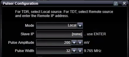
When connected the two STEPScope triggers, the STEPScopes must be configured into TDT mode. One STEPScope will be the pulser, and one will be the sampler. On the sampler STEPScope, open the Pulser Settings and enter the SlaveIP Address of the Pulser STEPScope. This will enable the Sampler to control the Pulser. Setting the Sampler's pulser mode to "Remote" will automatically set the slave pulser mode appropriately to generate the necessary pulse.
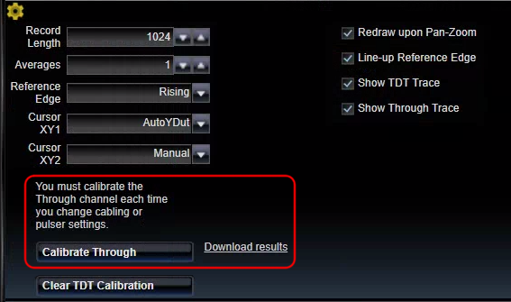
To perform TDT calibrations, click on the TDT Interface Tab. This will bring up the TDT App. Click on the TDT Settings wheel ![]() below the TDT chart. This will open the TDT Settings.
below the TDT chart. This will open the TDT Settings.
Follow the instructions in the GUI to calibrate the through channel.
After calibration, you can install your Device Under Test between the two STEPScopes.
See Also