BER Error Detector Application
BER Error Detector Application

The BER Error Detector Application provides basic BER information for each channel being tested. Which channels are shown is based on the Link Mode Status configuration. You can select a single channel, two channels, or a combined channel. When displaying a combined channel, you can also select to show the constituent sub-channels as well.
Information is updated while the analyzer is running. You can also press the Single button to run the analyzer for only one measurement interval. The duration of the measurement interval is selectable in the BER Strip Chart Application settings section.
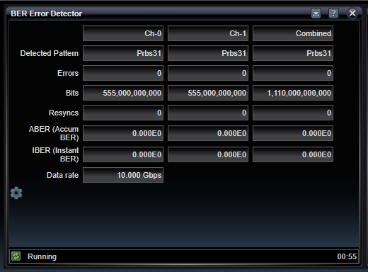
Detected Pattern
Indicates the detected pattern identifying which pattern type has been recognized on the incoming channel. Ch-0 and Ch-1 detection occurs independent of each other. Combined channel detection only occurs if the Interleaved Link Mode is selected. In this case, PRBS detection requires not only that the two individual channels detect the same PRBS pattern type, but also that when bit-interleaved together, the combination also forms the same PRBS type. Since individual channels may have different signal paths creating slight differences in timing, the automatic detection of combined channel PRBS patterns performs a bit-alignment process to search for a compatible bit-alignment between the two channels that creates a valid combined PRBS bit stream. The search occurs for +/- 127 bits. Some synchronization methods, particularly RamShift and InvRamShift, can take a few seconds to accomplish. If no pattern is detected, "None" is displayed. If a valid pattern is detected, it will be one of the following: AllZeros, AllOnes, Prbs7, InvPrbs7, Prbs11, InvPrbs11, Prbs13, InvPrbs13, Prbs15, InvPrbs15, Prbs20, InvPrbs20, Prbs23, InvPrbs23, Prbs31, InvPrbs31, RamGrab, InvRamGrab, RamShift, InvRamShift.
Errors
Indicates the number of errors encountered while running. This number only updates during pattern synchronization. This number may be presented in Decimal or Scientific format, as selected in the settings below.
Bits
Indicates the number of bits processed while running.This number may be presented in Decimal or Scientific format, as selected in the settings below.
Resyncs
Indicates the number of times the resynchronization with the incoming channel has been accomplished. Resynchronization can be done manually or automatically - based on detection of a high amount of detected errors known as the Resync Threshold, which is selectable in the Ch-0 / Ch-0 Status dialog.
ABER (Accumulated BER)
Indicates the total errors divided by total bits accumulated for the entire running session.
IBER (Instant BER)
Indicates the total errors divided by bits for the most-recent measurement interval number of seconds. The Measurement Interval is selectable in the settings below.
Data Rate
Indicates the per-channel bit rate in Gbits/sec. This will be equal to to the clock rate in GHz if the incoming clock is a full-rate clock. If it is a half-rate clock, it will be twice the clock rate.
BER Error Detector Settings

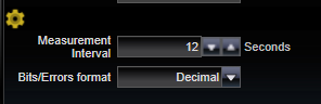
BER Error Detector application control settings provide configuration for how often measurements are made and what format they are displayed in.
|
Measurement Interval |
|
|
Seconds |
Setting for the measurement interval in seconds used to define the "Instantaneous" error interval and strip chart reporting interval |
|
Bits/Errors format |
|
|
Scientific / Decimal |
Format for error reporting |
See Also
Bit Error Location Analyzer Group Tabs