ELA Errors Modulo Histogram Application

The ELA Errors Modulo Histogram displays the location of individual errors relative to a repeating modulo factor. Different modulo factors can be very useful for analyzing if errors are coming from certain sources within your communications system. For example, if your system has a 32-bit bus, then seeing a histogram of errors modulo 32 will demonstrate if one particular bit of your bus is more-prone to error than the others.
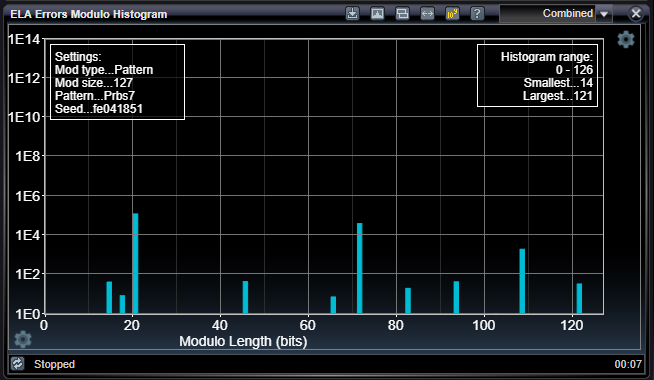
One very important modulo factor is the length of the pattern you are using for testing. In the image below, PRBS7 data pattern was being employed and errors are presented modulo the length of the PRBS7 data pattern, which is 127. You can see that errors are prone to occurring at a handful of locations within that 127-bit repeating distance. This demonstrates that errors are pattern-dependent. This is often produced by inter-symbol interference, for example.
ELA Errors Module Histogram Settings

The settings below enable you to configure the modulo factor for the ELA Errors Modulo Histogram application. The number of bits in each symbol is selected in the ELA Console settings

|
Modulo Type |
|
|
Pattern or Manual |
Selects how the modulo factor is determined. The modul factor may either be manually set to a particular number of bits, or it may be set to the length of the detected pattern type. |
|
Modulo Size |
|
|
Decimal, >0 |
Selects and displays the modulo factor in number of bits. For manual selection of modulo factor, use this setting to select the number of bits. For automatic pattern-dependent selection, this setting will be filled-in automatically once the pattern is detected. |
See Also
Bit Error Location Analyzer Group Tabs
Bit Error Location Analyzer Status Bar