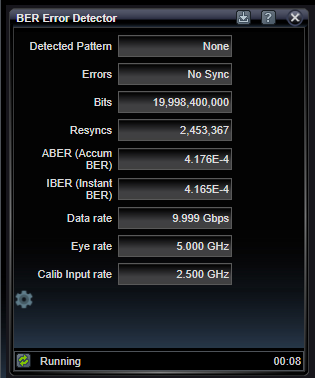
BER Error Detector Application
![]()
The BER Error Detector application displays the bit error rate-related information measured on the Calibration input of the Pattern Generator. This input supports measuring bit errors at sub-rate of the true Pattern Generator rate. This sub-rate divider value must be set to keep the actual Calibration channel rate under 2.5 Gbps. For example, when operating at 28 Gbps, a divide ratio of DIV16 must be used and the resulting Calibration channel rate will be 1.75 Gbps. When set, bit errors will be computed on every 16th bit of the data sequence. Because of the nature of pseudo-random data patterns, error detection will still synchronize on the same PRBS patterns as set in the pattern generator.

Detected Pattern
Indicates the pattern detected in the incoming bit stream. The detected pattern will be one of the following: AllZeros, AllOnes, Prbs7, InvPrbs7, Prbs11, InvPrbs11, Prbs13, InvPrbs13, Prbs15, InvPrbs15, Prbs20, InvPrbs20, Prbs23, InvPrbs23, Prbs31, InvPrbs31, Grab, InvGrab, None
Errors
Indicates the number of errors encountered while running. This number only updates during pattern synchronization. This number may be presented in Decimal or Scientific format, as selected in the settings below.
Bits
Indicates the number of bits processed while running.This number may be presented in Decimal or Scientific format, as selected in the settings below.
Resyncs
Indicates the number of times the resynchronization with the incoming channel has been accomplished. Resynchronization can be done manually or automatically - based on detection of a high amount of detected errors known as the Resync Threshold, which is selectable in the Calibration Input Status settings.
ABER (Accumulated BER)
Indicates the total errors divided by total bits accumulated for the entire running session.
IBER (Instant BER)
Indicates the total errors divided by bits for the most-recent measurement interval number of seconds. The Measurement Interval is selectable in the settings below.
Data Rate
Indicates the bit rate of the non-divided transmission in Gbits/sec.
Eye Rate
Indicates the eye diagramming rate which is a divided-down rate from the data rate. The Eye Rate divider is selectable in the Data Rate Status settings.
Calib Input Rate
Indicates the calibration input rate which is a divided-down rate from the data rate. This is the rate that BER measurements are based upon. The Calib Input rate divider is selectable in the Data Rate Status settings.
Click on the gear icon at the bottom left of the chart to access settings.
|
ABER (Accum BER) |
|
|
|
Report of accumulated BER since beginning of run |
|
IBER (Instant BER) |
|
|
|
Report on instantaneous BER for most recent report interval |
|
Bit rate |
|
|
GHz |
Report of transmission bit rate |
|
Eye rate |
|
|
GHz |
Report of eye rate on calibration input channel (see Eye Sub Rate) |
|
Calib rate |
|
|
GHz |
Report of calibration input rate (see Calibration Divider) |
BER Error Detector Settings

Less frequently used settings that effect the Calibration channel BER error detector include settings for the interval and formatting.
|
Measurement Interval |
|
|
Seconds |
Setting for BER interval in seconds used to define the "Instantaneous" error interval and strip chart reporting interval |
|
Bits/Errors format |
|
|
Scientific / Decimal |
Format for error reporting |
See Also
