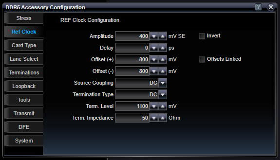
DDR5 Reference Clock Configuration
Two front-panel SMA connectors on the DDR5 Stress Accessory are used to support a REFCLK signal for DDR5 system testing. This REFCLK can be configured to support variable amplitudes, delay, offset, and offset coupling. In addition, the REFCLK signal can be inverted.

|
Amplitude |
|
|
mV |
Amplitude of each leg of the differentical REFCLK reference clock output. |
|
Delay |
|
|
ps |
Delay introduced in the output REFCLK signal. |
|
Offset (+) |
|
|
mV |
DC Voltage of the average signal on REFCLK+. |
|
Offset (-) |
|
|
mV |
DC Voltage of the average signal on REFCLK-. |
|
Source Coupling |
|
|
DC / AC |
Users can control if DC current is output from the Stress Accessory's REFCLK output by making this selection. An AC coupled output will not provide any DC offsets or DC current out the REFCLK outputs. |
|
Termination Type |
|
|
DC / AC |
Users define if the expected destination for the REFCLK is AC or DC coupled. AC coupled destinations can still have DC voltages applied to the outputs of the REFCLK. |
|
Term. Level |
|
|
mV |
User must set the expected termination voltage which allows the Stress Accessory to adjust its output amplitude and offset settings to deliver your required amplitude and offset into your load termination voltage. |
|
Term. Impedance |
|
|
Ohms |
User must set the expected termination impedance which allows the Stress Accessory to adjust its output amplitude and offset settings to deliver your required amplitude and offset into your load impedance. |
|
Invert |
|
|
On / Off |
The output REFCLK can be inverted using this control. Inversion has the effect of shifting the phase of the REFCLK by 180 degrees. This may be used in addition to the output delay setting to extend the range of variable delay. |
|
Offsets Linked |
|
|
On / Off |
In many cases, the positive and negative offsets for the two REFCLK output legs need to both be set to the same values. By making this selection, one set of controls will be used to program both the positive and negative legs. |
See Also