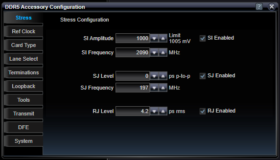
DDR5 Stress Configuration
The output clock from the Pattern Generator is provided as input to the Stress Accessory where jitter can be added to the clock so a jittered (stressed) clock can be reintroduced to the Pattern Generator on the ExtB (External B) connector to be used when generating data signals on either Ch0 and Ch1 of the Pattern Generator. In addition, a stand-alone sine wave generator is supported to output a programmable frequency and amplitude sine wave for conveniently adding sine interference to a test signal using a passive summing network in the data path.
Stresses can be enabled or disabled separately.
|
SI Amplitude |
|
|
mV |
The peak-to-peak amplitude of the sine wave to be generated. This sine wave is AC-coupled as it leaves the Stress Accessory. |
|
SI Frequency |
|
|
MHz |
The frequency (in MHz) of the output sine wave. Frequencies above 500 MHz are filtered for clean sine wave shape. Frequencies below 500 MHz can be generated, but these will take on a square shape and the frequency gets lower and lower. |
|
SJ Level |
|
|
ps p-to-p |
The peak-to-peak sine jitter to create. These peak-to-peak values are calibrated at a relatively high BER value, so those requiring specific SJ amplitudes in their test systems are encouraged to re-characterize the jitter amplitude under test system conditions before use. |
|
SJ Frequency |
|
|
MHz |
The frequency (in MHz) of the sine jitter to create. |
|
RJ Level |
|
|
ps rms |
The RMS value of the random jitter to create. Random jitter is created using an amplified and filtered calibrated noise diode. Output levels are calibrated at a relatively high BER value, so those requiring specific RJ amplitudes in their test systems are encouraged to re-characterize the jitter amplitude under test system conditions before use. |
|
SI Enabled |
|
|
On / Off |
Enable or disable just the SI features. |
|
SJ Enabled |
|
|
On / Off |
Enable or disable just the SJ features. It can be expected that the intrinsic jitter of the system is lower if the jitter is disabled, rather than being enabled and set to 0. There is no path switching when enabled or disabled, so overall delays are not changed depending on this control. |
|
RJ Enabled |
|
|
On / Off |
Enable or disable just the RJ features. It can be expected that the intrinsic jitter of the system is lower if the jitter is disabled, rather than being enabled and set to 0. There is no path switching when enabled or disabled so overall delays are not changed depending on this control. |
See Also